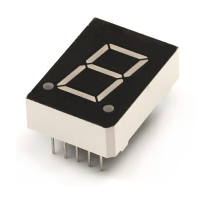
7 Segment Display – Common Anode – 0.56 inch – Standard Size (Pack of 150)
PRODUCT DESCRIPTION
(1) 0.56 Inch (14.20mm) Digit Height
(2) Low current operation
(3) Excellent color and font characteristics
(4) Colors: White, blue, red, yellow and green
(5) Gray or black color background
(6) Common Anode
(7) RoHs Compliant Part
(1) Pulse conditions of 1/10 duty and 0.1msec width, for long operating life, max. of 20mA recommended
(2) Reverse biasing of the dot matrix is not recommend, will cause damage to the leds
Reverse Voltage? ? ? ? ? ? ? ? ? ? ? - 3 V
Operating Temperature? ? ? ? -25 to 85 ?
Storage Temperature? ? ? ? ? ? ?-30 to 85 ?

71M6513H-IGT/F
Features
Line Frequency Range of 40-70Hz with the Same Calibration
7? Phase Compensation
RAM and RTC Battery Backup
22mW at 3.3V, backup power of 7.2W
Optional Flash Memory with Security
8-Bit MPU (80515)?One Clock Cycle for Each Instruction
LCD (168 Pixels) Driver
SSI Serial Output at High Speed
Time-of-Use Functions Using RTC
Hardware Timer Watchdog
Up to 22 General-Purpose I/O Pins are available.
64KB Flash and 7KB RAM
There are two UARTs for IR and AMR.
LQFP 100-Pin Package

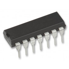
74F74N
These devices contain two independent positiveedge-triggered D-type flip-flops. A low level at the
preset (PRE) or clear (CLR) inputs sets or resets
the outputs regardless of the levels of the other
inputs. When PRE and CLR are inactive (high),
data at the data (D) input meeting the setup time
requirements is transferred to the outputs on the
positive-going edge of the clock pulse. Clock
triggering occurs at a voltage level and is not
directly related to the rise time of the clock pulse.
Following the hold-time interval, data at the
D input may be changed without affecting the
levels at the outputs.
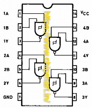
74HC00 Quad 2-Input NAND Gate IC (7400 IC) DIP-14 Package
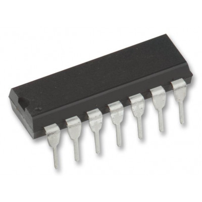

74HC02 Quad 2-Input NOR Gate IC (7402 IC) DIP-14 Package

74HC04 Hex Inverter IC (7404 IC) DIP-14 Package
74HC08 Quad 2-Input AND Gate IC (7408 IC) DIP-14 Package
74HC132
Features
? Buffering of inputs
? Wide working temperature range: -40?C to 85?C
?Fanout up to 10 LSTTL loads
? Significant power savings over LSTTL logic ICs
Application
- Used to make alarm/tamper detect circuit
- S-R latch