SN74ALS576BN
scription
These octal D-type edge-triggered flip-flops
feature 3-state outputs designed specifically for
bus driving. They are particularly suitable for
implementing buffer registers, I/O ports,
bidirectional bus drivers, and working registers.
These flip-flops enter data on the low-to-high
transition of the clock (CLK) input.
The output-enable (OE) input does not affect
internal operations of the flip-flops. Old data can
be retained or new data can be entered while the
outputs are disabled


SN74F08D
SN74F11N

SN74F174AD
This monolithic, positive-edge-triggered flip-flop utilizes TTL circuitry to implement D-type flip-flop logic with a
direct clear (CLR) input. Information at the data (D) inputs meeting the setup time requirements is transferred
to the outputs on the positive-going edge of the clock pulse. Clock triggering occurs at a particular voltage level
and is not directly related to the transition time of the positive-going pulse. When the clock (CLK) input is at either
the high or low level, the D-input signal has no effect at the output.
The SN74F174A is characterized for operation from 0?C to 70?C.

SN74F573DW
These 8-bit latches feature 3-state outputs
designed specifically for driving highly capacitive
or relatively low-impedance loads. They are
particularly suitable for implementing buffer
registers, I/O ports, bidirectional bus drivers, and
working registers.
The eight latches of the ?F573 are transparent
D-type latches. While the latch enable (LE) input
is high, the Q outputs follow the data (D) inputs.
When the latch enable is taken low, the Q outputs
are latched at the logic levels set up at the D
inputs.
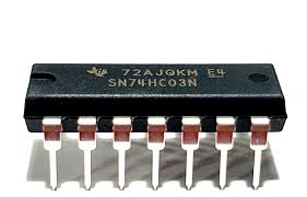
SN74HC03N

SN74HC08D

SN74HC164N
These 8-bit shift registers feature AND-gated serial
1? Wide Operating Voltage Range of 2 V to 6 V
inputs and an asynchronous clear (CLR) input. The
? Outputs Can Drive Up to 10 LSTTL Loads gated serial (A and B) inputs permit complete control
? Low Power Consumption, 80-?A Maximum ICC over incoming data; a low at either input inhibits entry
? Typical tpd = 20 ns of the new data and resets the first flip-flop to the low
level at the next clock (CLK) pulse. A high-level input
? ?4-mA Output Drive at 5 V
enables the other input, which then determines the
? Low Input Current of 1-?A Maximum state of the first flip-flop. Data at the serial inputs can
? AND-Gated (Enable/Disable) Serial Inputs be changed while CLK is high or low, provided the
minimum set-up time requirements are met. Clocking ? Fully Buffered Clock and Serial Inputs
occurs on the low-to-high-level transition of CLK.